
A gear pump is a common method to decrease the discharge pressure from the extruder, especially if the discharge pressure required by the die is relatively high. Temperature reduction and surge suppression are factors.
Temperature Reduction:
Decreasing the discharge pressure from the extruder will cause the specific rate to increase and the discharge temperature to decrease. A schematic for the axial pressure and temperature for a single-stage process is shown in Figure 3.
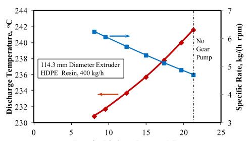
Here the pump is generating the pressure rather than the metering section of the screw, allowing the discharge temperature to decrease. For example, a process and die required a pressure of 21 MPa for operation at a rate of 400 kg/h for a high density polyethylene (HDPE) resin with a melt index of 0.08 dg/min (190 o C, 2.16 kg). If all of the pressure is provided by a single-stage 114.3 mm diameter extruder (screw design fixed), the discharge temperature will be about 242 o C, as shown by the operating curve in Figure 4. Here the specific rate for operation is 4.7 kg/(h rpm). But if a gear pump is positioned between the extruder and the die such that a portion of the required pressure is generated by the pump, then the specific rate for the operation of the screw will increase (causing the screw speed to decrease at a fixed rate) and the discharge temperature will decrease. For example, if the inlet pressure to the gear pump (discharge pressure from the extruder) in this case was 8 MPa, the extruder would discharge at 231 o C and operate at a specific rate of 6.3 kg/(h rpm). Thus, the discharge temperature could be decreased by 11 o C and the specific rate increased by 1.6 kg/(h rpm), as shown in Figure 4.
Some temperature increase will occur as the resin passes through the gear pump. This temperature increase is small compared to the decrease in temperature due to using the pump to increase the line pressure. The actual extrudate temperature will depend on the design and operation of the screw, the shear viscosity of the resin, the pressure contribution from the pump, and the design of the pump.
Surge Suppression:
Flow surging is defined as the oscillatory change in the rate of the extruder while maintaining constant set point conditions. Flow surging can originate from many different sources including improper solids conveying, melting instabilities, flow restrictions, and improper control algorithms [3,4]. Gear pumps are very effective at mitigating pressure surges originating from the extruder, and thus they have the capability of minimizing the resin consumption in the final product for a process with a mild flow surge to maintaining a level of production for processes with severe flow surging.
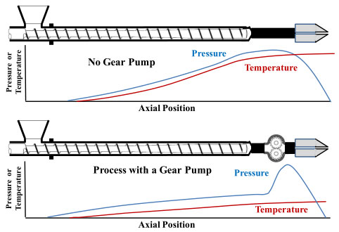
Figure 3. A schematic of the axial pressure and temperature for processes with and without a gear pump. The rates for both processes are the same, but the discharge temperature for the process with the gear pump is less than that for the standard process.
Extruder Discharge Pressure, MPa
Figure 4. Operation of a 114.3 mm diameter extruder running a HDPE resin at 400 kg/h as a function of discharge pressure.
A severe and random flow surging problem limited the production rate for a large-diameter, two-stage, vented extruder [5]. If it were not for a gear pump positioned between the extruder and die, this extrusion line would not have been operable. The surging did, however, limit the output of the line to about 70% of its potential rate. The maximum potential rate is the rate that the extruder can run at high screw speeds and with proper operation. The extruder was 203.2 mm in diameter and had a 40 length-to-diameter (L/D) barrel. A schematic for the extruder and gear pump arrangement are shown in Figure 2. The extrusion system was used to make a sheet product.
Steady-state operation of the extruder is shown by the first 400 minutes in Figures 5 and 6. The data for these figures were from the same production run. The extruder was running a high-impact polystyrene (HIPS) resin at 2250 kg/h and a screw speed of 99 rpm for a specific rate of 22.7 kg/(h rpm). This specific rate was about 14% higher than the specific rotational flow rate calculated for the first-stage metering section, indicating that a negative pressure profile exists in the section. The negative pressure gradient is expected for a first-stage metering section of a vented screw that is operating properly; i.e., the first-stage metering section was full of resin. To maintain the stability, the extruder screw speed was reduced such that extruder was operating at about 70% of its potential maximum rate. That is, at screw speeds higher than 99 rpm the extruder was more likely to transition from a stable to an unstable operation.
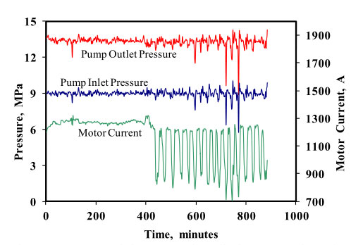
Figure 5. Pump inlet (extruder discharge) and outlet pressures and motor current for stable and unstable extrusion for a large-diameter extruder running HIPS resin.
During this first 400 minutes, the inlet pressure to the pump was relatively stable, and the discharge pressure to the die was also acceptable, producing prime product. At about 410 minutes into the run, the extruder started to operate unstably, as indicated in Figures 5 and 6. The processing change that caused the extruder to go from a stable operation to an unstable one was not known, but it could have been due to minor changes in the bulk density of the feedstock or cooling water fluctuations to the screw.
The root cause for the event and technical solution were provided earlier [3,5] and they are beyond the scope of this writing. As shown in Figure 6, the extruder screw speed was oscillating between 100 and 180 rpm during the period of the instability. During this unstable period, however, the gear pump control allowed the pump inlet pressure to oscillate at only a low level. The outlet pressure from the pump (pressure to the die) had a similar level of oscillation as in the inlet pressure, as shown in Figure 5. The oscillation in the outlet pressure, however, was acceptable for making prime product. Resin consumption was higher than normal during unsteady operation because the product was varying widely between the upper and lower control limits for sheet thickness rather than operating close to the lower control limit. If the pump would not have been on this line, prime product could not have been produced when the extruder was unstable. Although the pressure oscillation observed here was unacceptable, the pump was able to allow production during the time required to make the process modification to mitigate the surge.
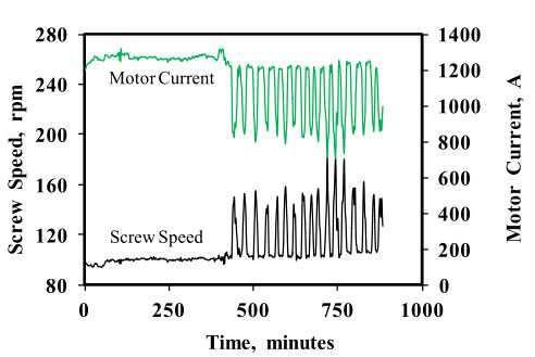
Figure 6. Screw speed and motor current for a large-diameter extruder running stable and unstable.