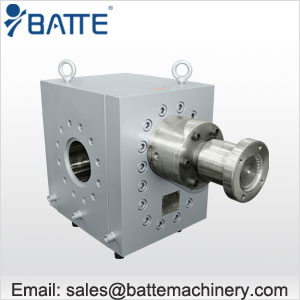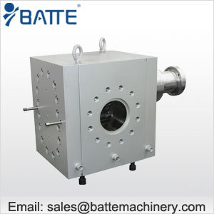
gear pump uses two meshing, toothed cogs to force water from the inlet of the pump through to the outlet. Figure No. 1 shows a simplified drawing of an external teeth gear pump on the left along with the alternate arrangement of internally pointing teeth.
The most common uses for gear pumps are to move chemical and petrochemical liquids that have relatively high viscosity; to supply fuel oil for burners or other facilities; and to transfer gasoline, kerosene, fuel oil and diesel oil. They also feature in hydraulic devices such as actuators, damper controls and elevators. In addition, they pump coolants, paints, bleaches, solvents, syrups, glues, greases, asphalt, petroleum and lubrication oils, and handle many general industrial applications.


Gear pumps, when properly designed and engineered, can offer many advantages. These include compactness, simplicity, easy serviceability, bidirectional and pulseless flow, self-priming, low net positive suction head requirement, high mean time between maintenance, high-pressure and high-temperature capability, precise and accurate metering, and availability in multiple seal configurations or with sealless magnetic drives.
Maintaining the close tolerances between the housing and the cogs is critical to efficient operation. The clearance between the edges of the teeth and the housing and the ends of the cogs and the back and front walls of the housing are very small. Between the teeth and housing it is in the order of 0.1 mm (0.004”) while the clearances between the front and back faces of the gears and the ends of the housing are only 0.025 mm (0.001”). The fine clearances reduce liquid re-circulation back from the high-pressure discharge to the low-pressure suction side and make these pumps one of the most efficient available.